Helicograph
Francis Penrose
1851
From the Official catalogue of the 1851 Great Exhibtion, London:
Registered screw and sliding helicographs for drawing volutes, scrollwork, and spirals of various kinds. The curves may be drawn on paper by means of an impression obtained from the disc by transfer paper they may be drawn in ink or with pencil by the sliding helicograph.
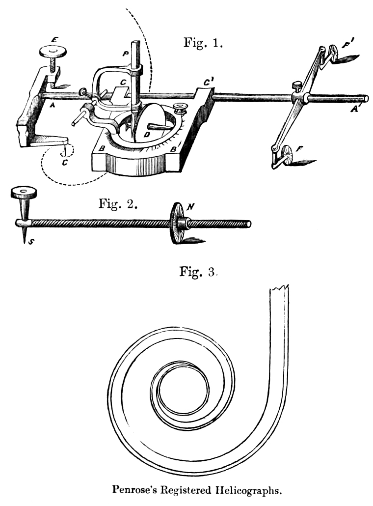
Fig. 1. Sliding helicograph. A heavy frame BB' slides upon a smooth straight bar AA', which passes through the guide sockets GG', forming part of the frame. Attached to the bar AA' is a point C, on which the instrument turns as a centre. Within the frame is a circular ring, carrying the axle of a small wheel or disc, D, fixed to one of its diameters. This ring, and the disc connected with it, may be placed at any angle with respect to the frame. The middle part of the frame is hollow, so that the wheel rests on the paper. By means of a gauge screw at E, and the carriage on castors FF', the instrument is adjusted to the proper level. A bar HK, which turns horizontally round K, a point in the frame, is provided with a pen and pencil socket, so that the describing point may be placed at any point within its range. The centre of gravity of the frame is so arranged that its whole weight falls directly upon the wheel, and the edge of the latter is milled so as to ensure its taking a firm hold of the paper, while the frame slides on the smooth bar. The spiral motion results from the obliquity of the axis of the wheel with respect to the smooth bar AA' when the instrument is made to revolve about the point C; the rate or pitch of the spiral depending upon the angle which the axis of the wheel makes with the frame. The graduations on the instrument are given on one side in degrees, and on the other in such angles as to make the longer and shorter radii in one revolution, to each other as the numbers 2: 1, 3: 1 . . . 10: 1, etc. The point C is placed at the same distance from AA' as the point where the circumference of the wheel touches the paper. The path of the wheel is the logarithmic spiral, when the instrument is made to revolve about the point C, and the pen P placed as near as possible to the wheel.
To describe a volute (fig. 3), the instrument is made to revolve about its centre, when the wheel turns round, and causes the frame to slide uniformly along the bar, until it carries the describing point as near to the centre as required. The frame being simply brought back along the bar, all the adjustments remaining unaltered, and the pen placed upon other points, a riband will be formed, preserving an uniformly decreasing thickness all the way. If a parallel line be desired, the pen must be shifted along the line of the axis of the wheel, and the latter made to traverse the same path as it did when the first line was drawn.
In drawing a volute, or other figure composed of several lines, it will generally be necessary that all the lines should be drawn either towards the eye, or away from it; as owing to a change in the action of the guide- sockets upon the smooth bar, when the motion is reversed, the angle is slightly affected. This does not impair the equiangular truth of each individual line.
Fig. 2 is the screw helicograph; S, the fixed centre; and N the wheel which works upon the screw.
Official catalogue of the Great exhibition of the works of industry of all nations, 1851. Class X. Philosophical, Musical, Horological and Surgical Instruments. (London 1851)
